Digital output has an open collector switching transistor with common IO Ground.
In most cases a power source for external device must be provided.
| Output State | Output switch state | Input state |
| ON | Sourcing current | Pull up (energized) |
| OFF | Relaxing | Not energized |
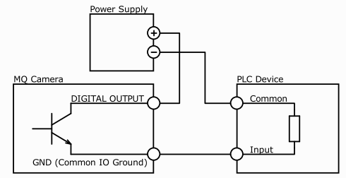
Figure 1. - Connecting Digital OUTPUT to a NPN-compatible PLC device input (biased)
Important Note:
If using this configuration take into account that Common Ground pole is biased by power supply also for Digital Input!
This type of connection is possible only when opto-isolated input is used (bidirectional in some cases) or when only one general opto-isolated input is used.
| Output State | Output switch state | Input state |
| ON | Sourcing current | Pull down (energized) |
| OFF | Relaxing | Not energized |
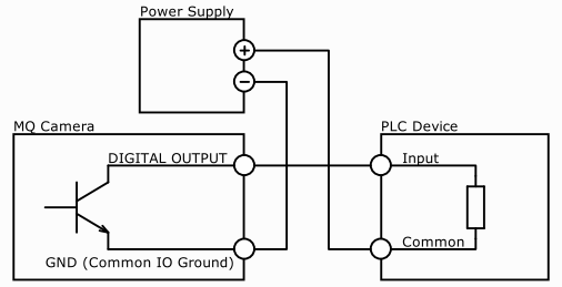
Figure 2. - Connecting Digital OUTPUT to a NPN-compatible PLC device input - more bidirectional inputs used
NOTE:
In this case bidirectional opto-isolated input must be used
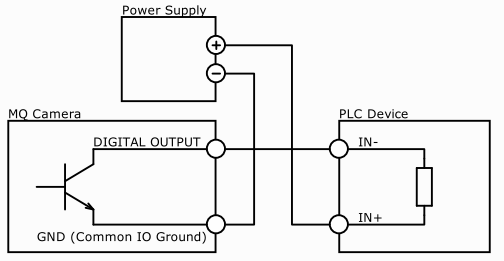
Figure 3. - Connecting Digital OUTPUT to a NPN-compatible PLC device - single input
| Output State | Output switch state | Input state |
| ON | Sinking current | Not energized |
| OFF | Relaxing | Pull up (energized) |
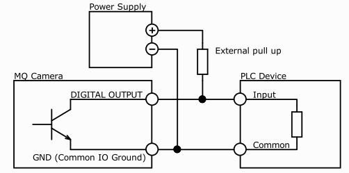
Figure 4. - Connecting Digital OUTPUT to a PNP-compatible device
Pull up resistor might be calculated as follow:
R=(Vpsu - Vinput) / Iinput
Where:
Vpsu - power supply voltage. Must be higher than required input amplitude
Vinput - required input amplitude
Iinput - input driving current (corresponding to input amplitude)
NOTE:
Take care about appropriate resistor power rating P(R)>(Vpsu - Vinput) * Iinput
LED might be driven directly by camera digital output.
Only series resistor must be used to set LED current.
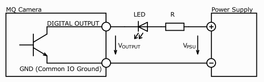
Figure 5. - LED Driving
LED series resistor might be calculated by following equation:
R=(Vpsu - Voutput - Vled) / Iled
Where:
Vpsu - power supply voltage (5V to 24V)
Voutput - voltage across digital output pins (see.Output transfer characteristic)
Vled - LED forward voltage (see table below)
Iled - LED current
NOTE:
Take care about appropriate resistor power rating P(RES)=Iled*Iled*R
Typical LED forward voltage
| LED Colour | Vled (typ.) | Vled (max.) | Note |
| Standard Red | 1.7V | 2.1V | |
| Super Bright Red | 1.85V | 2.5V | |
| Low power Red | 1.7V | 2.0V | |
| Orange | 2.0V | 2.1V | |
| Yellow | 2.1V | 2.2V | |
| Green | 1.9V | 2.5V | |
| Emerald Green | 2.1V | 2.7V | |
| Blue | 2.5V | 3.7V | |
| White | 2.8V | 3.8V | |
| Infra-Red | 1.3V | 1.8V | Optocoupler |
Do not connect inductive load RL directly to Camera Digital Output.
Transistor has to be used to prevent damage of output.
See image below for possible inductive load driving.
Resistor R can be connected to Digital Outputs and power supply to provide necessary bias current for transistor.
You should also use external diode to protect transistor from over voltage while disconnecting inductive load.
Keep in mind that this connection has an inverted logic.
Current will flow through load at start of camera.
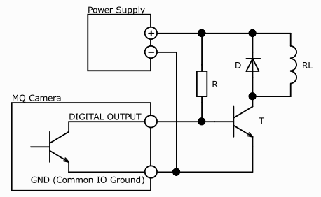
Figure 6. - Inductive load (Relay) Driving (inverted logic)
To get positive logic you can use second bipolar transistor.
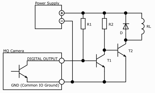
Figure 7. - Inductive load (Relay) Driving (non-inverted logic)
Digital output might be used to drive strobe controller according table below.
Driving trigger input of strobe controller
| Trigger polarity | Opto-isolated controller input | Output delay | Wiring | Description |
| Positive edge | Yes | 0.5us | Figure 1 | |
| Negative edge | Yes | 0.5us | Figure 3 | |
| Positive edge | No | 155us | Figure 4 | Not recommended in cases when short delay time is required. Output delay is much longer than in other wiring examples. Use external pull up in case that no pull at controller input is used. |
| Negative edge | No | 0.5us | Figure 4 | Note that external pull up is not used in this case. Assume that internal pull up at the controller input is used. |