Each sensor has different timing.
The real timing depends on multiple parameters:
In order to simplify the calculation of frame-rate or other parameters - use one of the following calculators based on camera sensor type:
Camera_Performance_Calculator.xlsm (deprecated)
For:
For:
Each image exposition is started automatically when possible.
This mode gives the highest fps (frames per second) that is possible on the sensor.
This Overlapped mode gives the highest number of frames per second.
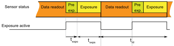
Sensor timing in Exposure Overlapped with Data Readout Mode
In this mode, the timing depends on the minimum Exposure Time and Data Readout Time.
Each image exposition is triggered with the input trigger signal.
This mode gives a lower fps value compared to Free-Run mode.
Most sensors use this mode when the input trigger is active.
This mode gives a lower fps value than Exposure Overlapped with Data Readout mode.
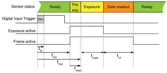
Sensor timing in Exposure Not Overlapped with Data Readout Mode
In this mode, the timing depends on the sum of:
| DownS | t itr [µs] | t exp [µs] | t eio[µs] | t expo[µs] | t rd[µs] | Notes | ||
| MU9 models: | ||||||||
| any | 200+ | |||||||
| xiQ/MQ models: | ||||||||
| any | 1.4 | 29 | 19/238 | 10 | 400+16.4*BWF*LC | N1, N2 | ||
| MD models: | ||||||||
| any | 2 | <3 | 26/165 | 1 | - | N3 | ||
| any | <70ns | <1 | <1 | <70ns | - | N4 | ||
Note N1: V(Input)=15V
Note N2: x in model name means all available models (M, C, R)
Note N3: Optoisolated Input and output are used. Input rising edge. For falling edge the delay is plus 48us
Note N4: Isolated High Speed Digital Lines (5V TTL only)
Table1 legend:
DownS = Current camera DownSampling (XI_PRM_DOWNSAMPLING)
t eio = Trigger (Digital Input) to Strobe (Digital Output) (on some models is listed: Off->On change / On->Off change)
t exp = Strobe (Sensor) to Digital Output (on some models is listed: Off->On change / On->Off change)
t expo = Start of exposition to Exposure Active Digital Output
LC = Current Line Count (XI_PRM_ HEIGHT)
BWF = Bandwidth Factor for maximum bandwith this is 1 when the bandwith will be lower BWF will rise (TBD)
t exps = Current Exposure Time set (XI_PRM_EXPOSURE)
Conditions: XI_PRM_DEBOUNCE_EN=0 (off).
Several sensors are capable to trigger exposure in overlap mode, so it is capable to reach the same fps value as in free run mode.
When the trigger period is longer than exposure and readout the signal waveform will look similar to Trigger mode without overlap.
However, when the trigger period will decrease the sensor will expose images in overlap mode.
In this case frame active signal will be all the time active.
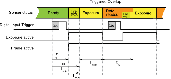
Sensor timing in Exposure Overlapped with Data Readout Mode
The maximum FPS can be calculated using FPS_calculator_CMV.xlsx .
For timing description please see the previous paragraph Triggered mode without overlap
| Camera Model | DownS | t itr [µs] | t exp [µs] | t eio[µs] | t expo[µs] | t rd[µs] | t fot[µs] | Notes |
| MQ042xG-CM | any | 1.4 | 10 | 11/224 | 0 | (64.5+5.375*LC)*BWF | 64.5 | N1,N2 |
| MQ022xG-CM | any | 1.4 | 10 | 11/224 | 0 | (37.625+5.375*LC)*BWF | 37.625 | N1,N2 |
| MQ003xG-CM | any | 1.4 | 10 | 11/224 | 0 | (92.8 + 3.78 * LC)*BWF | 92.8 | N1,N2, N3 |
| MQ013xG-ONV | any | 1.4 | <2 | 11/224 | 0 | (23*W+3300)/BW+(7.66*W+1106)*LC/BW | N1,N2,N4 | |
| MQ013xG-ON | any | 1.4 | <2 | 11/224 | 0 | TBD | N1,N2 |
Note N1: V(Input) = 15V
Note N2: 8 bit per pixel maximum bandwidth (TBD)
Note N3: Exposure is delayed for short exposure times. If (t exps < t rd) then t eio = t eio + (t rd-t exp) approx.
Note N4: VITA1300
Table2 legend:
DownS = Current camera DownSampling (XI_PRM_DOWNSAMPLING)
t eio = Trigger (Digital Input) to Strobe (Digital Output) (on some models is listed: Off->On change / On->Off change)
t exp = Strobe (Sensor) to Digital Output (on some models is listed: Off->On change / On->Off change)
t expo = Start of exposition to Exposure Active Digital Output
t exps = Current Exposure Time set (XI_PRM_EXPOSURE)
W = Image width(XI_PRM_WIDTH)
LC = Current Line Count (XI_PRM_ HEIGHT)
BW = Bandwidth in Mbit/s
BWF = Bandwidth Factor see table below
Conditions: XI_PRM_DEBOUNCE_EN=0 (off).
Bandwidth factor is a number reflecting the ratio between the maximum pixel clock frequency and the current pixel clock frequency calculated from the Bandwidth Limit.
BWF = F max / F limit
Where F max is the maximum possible pixel clock frequency for the given sensor (in MHz) and F limit is the current pixel clock frequency which depends on the bandwidth limit parameter set in the API (XI_PRM_LIMIT_BANDWIDTH). F limit is set in 1MHz steps and can not go lower than F min.
| Camera Model | F max [MHz] | F min [MHz] | F limit [MHz] | Note |
| MQ042xG-CM MQ022xG-CM |
48 | 5 | ((129*BWL)/(1024*BPP))*((12+LC)/LC)*(W max/W) | N1 |
| MQ003xG-CM | 43 | 38 | ((325*BWL*)/(316224*BPP))*(13+LC/2)*(W max/W) |
Note N1: Sensor is capable to limit the number of channels for readout.
The presented formula is valid down to half of the maximum bandwidth. Will be updated.
Table3 legend:
BPP - number of bits per pixel of the transport pixel format
BWL - currently set bandwidth limit in Mbit/s
W - image width”
W max - maximum possible image width